Reliserv Solution’s substation automation system is a collection of hardware and software components from reputed OEM’s that are used to monitor and control an electrical system, both locally and remotely. We have the best substation automation system which also automates some repetitive, tedious and error-prone activities to increase the overall efficiency and productivity of the system.
Why to automate power substation? What do you get?
Reliability and availability of quality power is need of an hour. It gets difficult to achieve the same using the conventional methods. With Substation Automation we create reliable system with minimum human intervention and subsequently reducing human errors. It is evident that substation automation if implemented improves the operating efficiency of the system. Using substation automation we can bring complete substation at a single desk with complete Monitoring, Control and report generation facilities. Further all the collected data can be used with various tools for analysis and decision making.
We Reliserv Solution believe “A good product and reliable services bring high profitability”
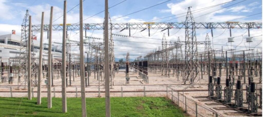
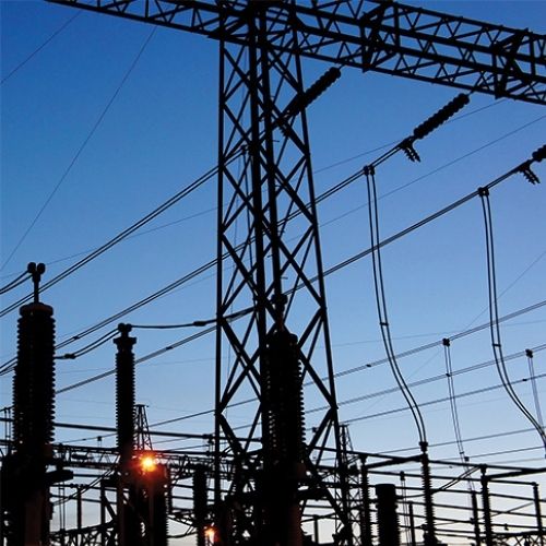
Modern Substations
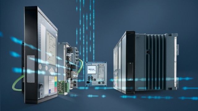
With the introduction of microprocessor technology, digital protection and control devices became more intelligent. New intelligent electronic devices (IEDs) can collect and record information on many different parameters of a system, process them based on complex logic in a fraction of a second and make decisions on abnormal situations to send control commands to switches and breakers to clear the fault.
IEDs can now send information to a local or remote user via different types of communication. This gives operators more flexibility on how and when to process the information to provide a fast recovery time from an interruption in the substation.
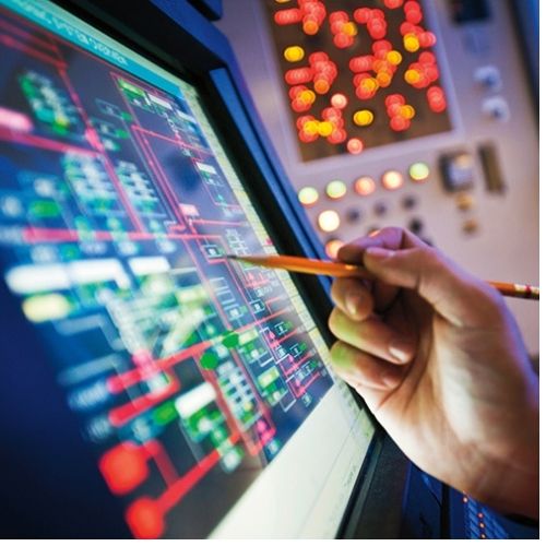
With more information remotely available, new supervisory systems were developed to facilitate the task of a system administrator in the control centre. A Supervisory Control and Data Acquisition (SCADA) system can collect information from various IEDs in an electrical system via different methods of communication and then control and monitor them.
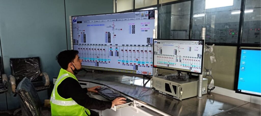
A Human Machine Interface (HMI) is deployed in each substation to provide operators with the local control and monitoring capabilities that are often necessary during the configuration, commissioning or maintenance of the substation.
Digital substation, auto configuration and standards
Digital control and protection technology has been evolving since the first introduction of digital devices. The more intelligent and capable the devices became, the more responsibilities that tended to be transferred from human to device. Unlike early digital technologies – where an operator had to work with bits and bytes on a primitive user interface to define every parameter of the system and make sure all elements of the system are correctly configured to make the processing and communication work– new technologies let users focus more on high-level aspects of the system architecture by taking care of the tedious task of defining every single detail in the system configuration.
In the beginning of the digital era, each manufacturer had its own way of interpretation and implementation of different elements in an intelligent system. New standards have been developed to make sure devices from different vendors will function in the same predefined way. This gives users more flexibility and freedom to choose functions that suit them better without having to focus too much on manufacturer.
Big data, non-operational data processing

In the earlier years of digital technology, limited data points were available on each device and the high cost of communication – as well as a slow data exchange rate – would render it impractical to collect a high amount of data from each substation. Only necessary operational data was sent to control centres and communication lines were cautiously programmed to minimize the bandwidth and communication cost.
Rapid evolution of communication and process technologies now offers system administrators the luxury of polling more and more operational and non-operational data points from their substations. This information can now be processed in a variety of ways using different software to more efficiently monitor an electrical system. This technology improvement provides for greater sight on overall health and useful information for other applications such as condition-based maintenance and asset monitoring.
Substation information collection
Substation information is collected via communication protocols, physical communication and other substation technologies.
Communication protocols
A communication protocol defines a set of rules for transmitting data between two or more communication parties. Protocols have been developed to serve various purposes based on specific requirements of that application.
Most of the early protocols in the electrical automation industry were proprietary protocols developed by device manufacturers. Although proprietary protocols work especially well with devices from the same manufacturer, lack of interoperability – along with vendor dependency – pushed electrical companies toward standard and open-source protocols. Today, device manufacturers have adopted popular standard protocols. As a result, proprietary protocols have been almost completely phased out from the industry. Unlike slow and error-prone older protocols, newer protocols can deal with different communication mediums, recover from communication sever failures and deliver information in a more robust way.
Although older protocols such as MODBUS are still used in substation automation, most of the systems have already adopted protocols like DNP3 (North America) and IEC 60870 (Europe) as their de facto default protocol.
In addition to the set of rules, control headers and error recovery mechanism, traditional protocols also define the structure of a “point list.”
Although traditional protocols require more time and effort during configuration and commissioning, they are popular in the automation industry because they are easy to understand, configure and troubleshoot.
Physical communication: Modem, serial, copper ethernet, fibre, radio, cellular
Being connected to a substation and retrieving vital information from remote devices has always been a challenge for system designers. Not all the substations are of the same size or importance. Early remote monitoring started by using modems on telephones or leased lines. Initial efforts were made using a gateway device in the field that would concentrate information it was receiving from serial devices and send that information to a master station using a modem based on a predefined time schedule. Concentrating information would improve the communication (and reduce the cost) as sending data points in one burst would reduce the communication time – as compared to sending small data packets from different devices over a longer period of time.
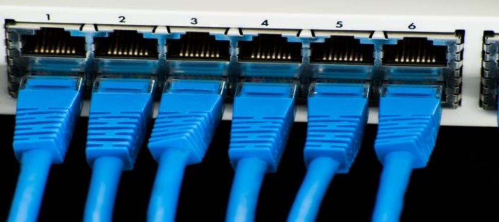
In modern substations, most devices communicate via ethernet links. Data from different devices is sent to the control centres via various communication mediums. Utilities generally prefer to install their own inter-sub communication infrastructure using fibre-optic links or radio mesh systems but in some cases, especially in remote areas or smaller substations, using cellular modems becomes more practical.
Substation technologies: Redundancy, time stamping, time synchronization, logs
As IEDs improve and implement more functions, new applications can be developed to better leverage these new capabilities. With more accurate and up-to-date information from system elements, IEDs can provide users with better insight on system operation and general health.
Although redundancy is not a new concept, new technology makes it easier to implement and manage redundant devices. In a hot standby configuration, two devices (e.g. a gateway) can be configured in a group where one acts as ‘’active’’ while the other one stays in ‘’standby.” The standby device constantly monitors the status of the active device while the active device receives information from other parties, updates both its internal database and the database of the standby unit and sends information to one or multiple clients. If the standby device detects that the active unit is no longer communicating, it assumes (after a predefined period of time) that the active device is no longer functional and takes over the control and continues sending/receiving information.
Sophisticated redundant systems also support virtual addresses. A virtual address will hide physical device addresses, so the transition stays transparent as long as the virtual address is used for the communication.
Time synchronization devices and methods such as GPS clocks and IRIG-B signals have been used in substations for quite a while. The goal is always to keep the internal clock of the devices in a system synchronized. Time synchronization is also critical in a protection system.
New substation automation technologies offer new methods of time synchronization. Unlike older systems where the time signal was distributed using hard-wired links (IRIG-B wires, serial cables), new time protocols leverage the communication infrastructure to distribute time signals. Some communication protocols (e.g. DNP3 or IEC-104) as well as NTP (Network Time Protocol) and SNTP (Simple Network Time Protocol) can already provide sufficient precision for many applications. However, the high-time precision that is required in mission-critical applications cannot be achieved using these methods.
In recent years, Precision Time Protocol (IEEE standard 1588) was introduced to leverage existing network infrastructure to provide sub-microsecond time accuracy for devices in control and protection systems.
Time synchronization methods | Typical precision |
Communication Protocols | < 100 ms |
NTP | 1 ms – 10 ms |
IRIG | 1 µs –10 µs |
IEEE 1588 | 20 ms – 100 ms |
With more processing power and internal storage, IEDs can now produce more information regarding their internal activities. Logging this information and sending it to a control centre will provide operators more visibility on what happens in the device and, in case of a problem, gives hints on where to start the troubleshooting. A Syslog server can also be installed in the system to collect these log files and store them in a central repository for further analysis.
Event files can also be generated based on some changes on internal status of a device or data points. For example, an oscillography file captures the value changes on some system parameters (e.g. voltage, current, phase angle) during a fault. Analyzing this file provides system engineers with valuable information on the status of the system right before and after a fault occurs.
Similar to log files, event files can be collected centrally and made available for a wider range of users. This central repository also makes sure information won’t be lost from the devices – as they still have limited storage space as compared to a local server.
Substation automation elements
Different components are used in a substation automation control system to collect information on various parameters of the system, to monitor them and – in a higher level – to analyze this information and make decisions based on the outcome of the analysis. Although some devices often cross the line between control and protection systems, they can generally be categorized into these five groups:
1. Gateway (automation platform)
Gateways are initially employed to collect information from serial devices and make this information available for a remote user, but they also include support for more functions that are required in a substation. A typical modern gateway has a modular design and can host multiple serial and ethernet ports in fiber or copper. Its internal storage has adequate space to collect thousands of files and it supports sophisticated protocols and time synchronization methods.
Data Concentration
As a data concentrator, a gateway can collect information via several serial or ethernet ports from the devices in a substation and make them available to remote users. Although the data concentration function is not as important as it previously was, it still adds a lot of flexibility to the system. A data concentrator can also offer more storage to maintain log and event files as compared to internal storage of the IEDs.
Using a data concentrator also simplifies system configuration on the SCADA side. Instead of individually setting up the devices in the substation in the SCADA system, only one gateway with one communication link and one set of points is required to be integrated in the SCADA system. When adding, removing or changing a device in the field, the SCADA system only needs to update the point list without changing the communication link parameters.
Protocol translation
As a data concentrator, a gateway can collect information via several serial or ethernet ports from the devices in a substation and make them available to remote users. Although the data concentration function is not as important as it previously was, it still adds a lot of flexibility to the system. A data concentrator can also offer more storage to maintain log and event files as compared to internal storage of the IEDs.
Using a data concentrator also simplifies system configuration on the SCADA side. Instead of individually setting up the devices in the substation in the SCADA system, only one gateway with one communication link and one set of points is required to be integrated in the SCADA system. When adding, removing or changing a device in the field, the SCADA system only needs to update the point list without changing the communication link parameters.
Data distribution
Once data points are concentrated in the gateway, they can be available to various remote and local users via different protocols. This feature of the gateway is especially useful in cases where a device has limited outbound communication. Different users with varying interests may want to access the same device at the same time.
Logic processing
Since a gateway collects data points from different devices in a substation, it is the ideal place to implement some logic for control and operation purposes. By using a well-known programming language such as IEC 61131, input points can be created, and output commands can be issued based on some predefined logic. These points can also be sent to a control and monitoring system in the master station.
2.Distributed I/O (inputs/outputs)
Although the terms RTU and gateway are used interchangeably these days, first-generation RTUs were devices with limited communication capabilities that were used to convert hardwired signals into binary or analog data points.
With the evolution of digital relays, most system parameters became digitally available directly from relays and meter-over-ethernet links and via new protocols – and the demand for high-capacity RTUs was reduced.
However, there are still some hardwire signals (e.g. breaker monitoring and control, cabinet door safety switch, transformer oil gauge) that need to be monitored or controlled by remote users – sometimes even separately from the protection system.
A distributed I/O device can convert a limited number of Input/Outputs into digital values and communicate those values via a standard protocol through serial or ethernet link
3.IEDs (protection relay, smart meters)
An IED (Intelligent Electronic Device) is a microprocessor-based device with some processing and communication capabilities. The biggest category of IEDs in a substation is protective relays. This device can receive information from CTs, PTs or other type of sensors, make control or protection decisions based on some algorithms and issue commands to other devices such as breaker and switches.
Although sensor signals are still mainly in hardwired form, modern IEC 61850-based substations can communicate digital information between sensors and relays using sample values or GOOSE protocols. A digital relay can also generate and save log, event and oscillography files.
Digital meters are another type of IED that can measure and record main system parameters and communicate them to a control centre.
4.SCADA
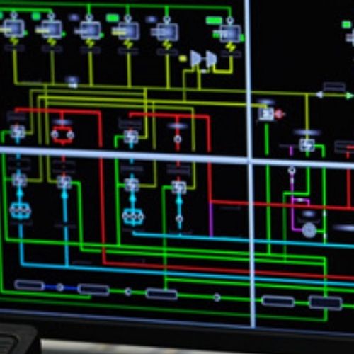
Single-line diagram
A single-line diagram is an interactive graphical representation of the grid system via which an operator can monitor different parameters of the system and issue commands as necessary. A SCADA single-line diagram generally consists of an overview of the system plus multiple detailed pages for different components of the system to which an operator can navigate.
Real-time trending
Unlike single-line diagrams that show the components and connection of the system, the real-time trending function provides the operator with a real-time chart that monitors the values it receives from devices in the substation. An operator can add one or several points to the chart and follow the real-time value changes for better analysis of the system.
Historian
Recording information is another important function in a SCADA system. Except for some buffering capabilities, most IEDs and gateways have insufficient internal storage to maintain a record of real-time value changes for an extended period of time. One of the main tasks of a SCADA system is to record the real-time values it collects from the devices in the field. This information is saved in a relational database. The recorded information can also be accessed directly from the database using a third-party application for further analysis.
Event and alarm management
Event and alarm management is also part of the standard functions offered by a SCADA system. An alarm can be raised by the SCADA system in an alarm window based on predefined criteria. The operator can then acknowledge the alarm and clear it when the value of the point the alarm was created on goes back to its normal status.
Like alarms, events can also be generated based on the status of the data points collected from the field. Contrary to an alarm management system, an event management system doesn’t require an operator’s intervention – as generally events are not considered critical.
User notification
One of the main tasks of a SCADA system is to provide the necessary information to the right people in a timely manner. In a new SCADA system, the software administrator can assign notifications for different alarms and events to specific users or a group of users and send them email or text message notifications based on that list.
5.Substation HMI
A Human Machine Interface (HMI), is a stripped-down version of a SCADA system that is used locally in a substation – especially during commissioning and maintenance. An HMI only monitors local devices and generally doesn’t have a historian capability. An operator can use a HMI system for operating the devices or to verify the current status of the system. A HMI could run on a local computer substation, but a better solution would be to use a modern gateway that supports a built-in HMI function. The HMI function on such a gateway would be locally accessible via a touchscreen monitor directly connected to the gateway or locally/remotely through a web connection.
Single-line diagram
The concept of the single-line diagram in a HMI system is the same as in a SCADA system. A graphical representation of the system helps the operator to visually investigate the current state of the substation and sends commands to the control. A HMI has fewer single-line diagram pages as it only needs to represent its own substation.
Alarm management
Except for the fact that HMI alarm management only takes care of local alarms and events, the rest of the functionality is similar to a SCADA system alarm management system.

System health information
Another function of a HMI system is to show some form of a summary on the general health of a substation. Information such as the number of successful and failed communications, gateway CPU and memory usage and the software version can be shown in a graphical form, so an operator can evaluate the overall condition of the system at a glance.
Commissioning tools
Commissioning tools is a set of tools on a HMI system that offer an operator various functions that can improve or speed up the process of testing and commissioning during a substation installation or troubleshooting session.
It shows real-time value of the points received by a gateway, the ability to simulate some values and other functions such as reading logs or events can provide better insight into the current status and faults that may occur during the operation.
Automation Solutions
Substation Automation using RTU/PAS
Reliable transmission and distribution of electricity is the key to a Smart Grid and an integral requirement for Utilities. Substation Automation Systems (SAS) as a comprehensive part of substation control and monitoring solution provides functions such as advanced power system management and monitoring of the condition of the equipment while asservice.
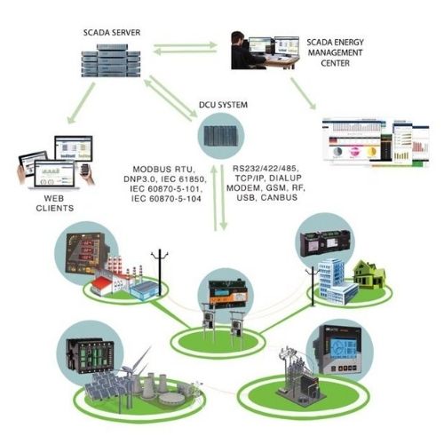
Reliserv is the leading enablers of substation automation solutions including IEC 61850 /104 /101 /103/61850 & Modbus. Reliserv substation automation offerings comply with IEC 61850 standard,, ensuring key to protection, control, automation, monitoring and real-time communications capabilities of substations with existing legacy as well as systems for future. Our smart automation reduces operational and maintenance costs, thereby increasing the performance of the plant and improving the efficiency in operations.
What is SCADA
Supervisory control and data acquisition (SCADA) is a system of software and hardware elements that allows industrial organizations to:
- Control industrial processes locally or at remote locations
- Monitor, gather, and process real-time data
- Directly interact with devices such as sensors, valves, pumps, motors, and more through human-machine interface (HMI) software
- Record events into a log file
SCADA systems are crucial for industrial organizations since they help to maintain efficiency, process data for smarter decisions, and communicate system issues to help mitigate downtime.
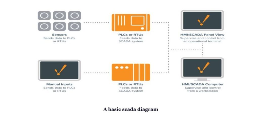
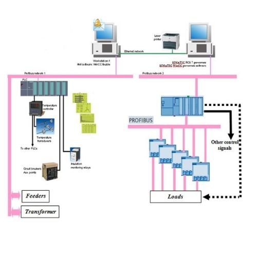
The basic SCADA architecture begins with programmable logic controllers (PLCs) or remote terminal units (RTUs). PLCs and RTUs are microcomputers that communicate with an array of objects such as factory machines, HMIs, sensors, and end devices, and then route the information from those objects to computers with SCADA software. The SCADA software processes, distributes, and displays the data, helping operators and other employees analyze the data and make important decisions.
Energy Monitoring Solutions and IOT Linkup for Clients
In this Energy monitoring system, SCADA is used to visualize current reading of energy meters as well as to collect the historical data for future usage. Also, SCADA is used to generate the report of necessary readings like power consumption in the hourly, daily, weekly and monthly format.
PLC Automation Solutions
PLC automation is a process automation solution, wherein the Process is automated and customized as per client needs in a given premise. We offer different sizes and types of PLC:
- A compact PLC is a PLC where the number of inputs and outputs are fixed.
- A modular PLC is a system that is comprised of multiple inputs and outputs as is required by the user. Multiple modular units can be built together on a rack to suit the purpose of the user.
- This reduces the time and improves process accuracy in the system.
Product Supply Solutions
We are channel partners of Siemens and traders for Schneider, GE and ABB. We supply various products from OEM’s with add on services for proper installation. We Supply:
- Numerical Relays. – Siemens, Schneider, GE and ABB
- LV Switchgears
- MV Switchgears
- Control and relay panels
- Power Quality Meters
- Auxiliary Relays –Brand names
- Automation Products
Rental Solutions
Testing kits are an integral part of testing. A Good test kit ensures proper testing procedure and reliable test results. We offer omicron (Austria) make kits that are No.1 in field testing and recommended by experts. We offer:
- Secondary Injection Kit (CMC356)
- CT analyser(Advanced)
- PT Analyser (Votano)
- Tan Delta (CPC 80 + CP TD12/15)
- Primary Injection Kit (CPC 100)
- CB Analyzer (CIBANO 500)